
Quick answer: For CNC-produced metal signs, send a correctly scaled vector file—usually an editable AI, EPS, SVG or vector PDF—and a production DXF with closed cut contours, separate inner and outer paths, no open strokes, and text converted to outlines. DXF is the preferred manufacturing file because it preserves 1:1 geometry and lets the factory assign layers for cutting, etching, bending and drilling. JPG and PNG files are useful references, but they normally need to be redrawn before production.
A metal sign can look approved on screen and still arrive with thin strokes, oversized mounting holes or a poorly fitting return because the artwork was never prepared for fabrication. The difference is not simply the file extension. It is whether the geometry is closed, measurable, layered and complete. This guide explains how to prepare custom 3D letters and flat metal sign components so that the quote, toolpath and finished product all describe the same design.
Which file format should you send for a metal sign?
| Format | Best use | What to watch |
|---|---|---|
| DXF | CNC cutting, drilling and bend-line preparation | Use millimetres, 1:1 scale, closed contours and clearly named layers. |
| AI or EPS | Editable logo artwork and design intent | Convert text to outlines and remove linked-image dependencies. |
| SVG | Web-origin vectors, simple logos and portable line art | Check that fills, strokes and clipping paths do not conceal open geometry. |
| Vector PDF | Approval drawings and supplied specifications | Confirm page scaling and whether the PDF contains true vector paths. |
| JPG or PNG | Visual references, textures and installation context | Raster pixels do not define a reliable cut path. |
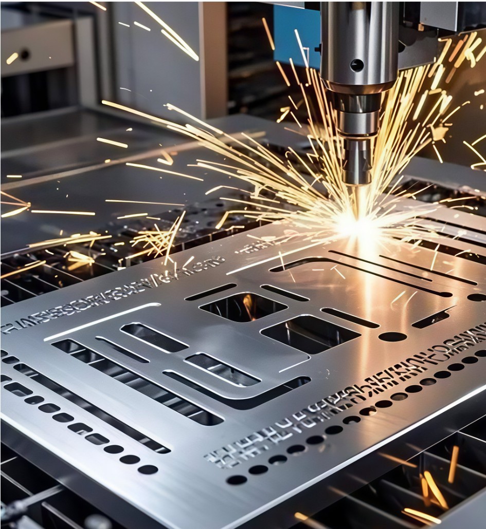
Sending several formats is often more useful than sending one. An editable vector shows the intended logo, while a prepared DXF defines production geometry. A dimensioned PDF or marked screenshot can then explain which face is visible, where letters return, and how the sign will be mounted.
Why DXF is usually the production file
DXF is a drawing exchange format rather than a finished decorative design. Its value in signage is that it describes geometry directly: lines, arcs, polylines, circles and layers. A CNC programmer can separate the outside profile from letter counters, place holes on a drilling layer, put bend lines on a separate layer and apply the correct tool or lead-in.
A DXF is not automatically production-ready. Two files can share the same extension while one contains a single open outline and the other contains nested, closed contours. Before approving a file, open it in a CAD viewer and zoom into the smallest corners, counters and connection points. If the path crosses itself, stops before joining or includes construction guides, the fabricator may have to redraw it. The Autodesk CAD documentation is useful background, but the factory drawing standard still controls how layers and dimensions should be named.
What should a sign-ready DXF contain?
- One agreed scale. Draw at 1:1 and use millimetres or state the unit explicitly. A drawing that looks correct at “fit to page” can be wrong when imported.
- Closed cut contours. Every cut outside and every internal hole should form a clean closed loop.
- Separate production layers. Use names such as CUT, ETCH, DRILL, BEND and REFERENCE rather than relying on colour alone.
- Converted text. Fonts can substitute between computers. Convert final lettering to outlines after confirming spelling and spacing.
- Minimum stroke control. Thin decorative serifs may disappear, bend or distort after cutting, welding and finishing.
- Mounting and service features. Show fixing holes, anchor centres, cable entries and any LED service access before the part is cut.
- A reference drawing. Supply a dimensioned overview and elevation so the DXF can be understood in context.
How do vector files differ from JPG and PNG artwork?
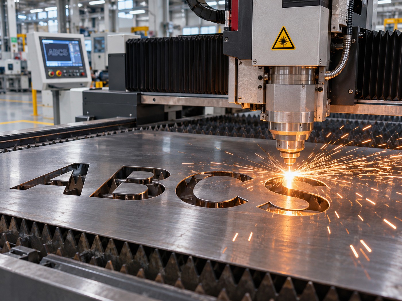
An SVG, AI or EPS file usually stores paths and fills mathematically. A JPG or PNG stores pixels in a grid. The distinction matters at the edge: a vector path can be measured and cut, while a pixel edge must be interpreted. Auto-tracing a low-resolution logo may introduce wobbles, rounded corners, double lines and stray islands that are difficult to see on a phone screen.
SVG is capable of excellent precision, but web SVGs frequently contain clipping masks, hidden groups and strokes set to “outline.” Check the SVG in vector-editing software before treating it as a cut file. The W3C Scalable Vector Graphics specification defines the format broadly; it does not guarantee that a particular SVG is fabrication-safe.
Raster artwork is still useful. A photograph can show the intended finish, a screenshot can identify the correct logo version and a lighting mock-up can communicate brightness. Label those files as references so nobody mistakes them for the geometry source.
How should kerf be handled in a metal sign file?
Kerf is the material removed by the cutting process. If a 5 mm slot is drawn for a 5 mm LED strip, a real kerf can make the finished opening larger than intended. The same issue affects acrylic backers, trim caps and letters that must fit into a frame.
Do not guess one universal offset. The fabricator should apply kerf compensation by material, thickness, machine and cut method. A practical drawing package keeps the nominal design geometry intact and documents critical fit dimensions. For narrow internal cutouts, ask whether the design should be enlarged, simplified or changed to a different production method.
What must be planned before cutting a channel letter?
CNC files should not be developed in isolation from the rest of the letter. The front-lit channel letter construction includes a face, return, back, trim, LED modules, wiring and mounting method. A file that cuts every letter at the same nominal size can create different visual stroke widths after welding and coating.
For illuminated signs, coordinate the cut drawing with the LED module layout and wiring plan. Cable holes should not fall behind a module, intersect a mounting screw or become the low point where water accumulates. Service access also matters: a beautiful closed back becomes expensive if the power supply or wiring must be exposed later.
Large fabricated letters need bend lines, tabs or removable return templates. Small letters may need a fixture or tack-welding tab that is cut away after assembly. Those details should appear on the drawing before material is committed. The guide to channel-letter sizes explains why the same font does not remain legible at every height.
How do you prepare artwork step by step?
- Confirm the final wording. Lock spelling, punctuation, registered symbols and language before converting text.
- Choose the visible side. Mark which face is cosmetic and which surfaces may show weld or fixing marks.
- Clean the vector. Remove duplicate paths, stray points and zero-width gaps; join interrupted lines.
- Set the scale and units. Use a measured letter height and baseline rather than “looks about right.”
- Assign layers. Separate cut, etch, drill, bend, fold, reference and packing marks.
- Check fit-critical features. Review holes, slots, trim depth, acrylic clearance, return width and service access.
- Produce a proof. Supply a dimensioned drawing and a clean visual proof for customer approval.
- Record the approved revision. Put a revision date in the file name so production does not open an older design.
The broader custom signage quote checklist is useful here. A complete artwork package reduces assumptions and prevents the quote from excluding operations that were never visible in the initial image.
What should be included in an RFQ package?
- AI, EPS, SVG or PDF artwork plus a prepared DXF when available.
- Overall dimensions, letter height, stroke width and quantity.
- Material and thickness, including grade and finish.
- Front-lit, halo-lit or non-illuminated construction.
- Voltage, power location, dimming and whether LEDs must be serviceable.
- Mounting surface, wind exposure, installation height and fixing method.
- Colour standard and an approved finish sample.
- Packing, transport and delivery requirements.
For a full manufactured assembly, compare the supplied drawing with the expected custom metal letters construction and with the steel, aluminium and stainless-steel material guide. The DXF controls shape; material and construction determine how that shape will behave outdoors.
Which changes should trigger a new drawing revision?
A revision is required when the change affects geometry, fit, finish or compliance—not only when the design looks different. Moving one mounting hole, changing sheet thickness, widening a return or switching from front-lit to halo-lit can alter the toolpath, drill positions, LED clearance and packing frame. Keep the approved drawing visible during production so a late email instruction does not overwrite the controlled file.
Frequently asked questions
Can you manufacture a metal sign from a JPG?
It may be possible after redrawing and approval, but the image itself is not a reliable production path. A clean vector source or a paid redraw reduces ambiguity and iteration.
Is PDF better than DXF?
They serve different purposes. A vector PDF is excellent for visual approval and notes; a layered DXF is usually better for CNC programming. Supply both when practical.
Should the factory add kerf compensation?
Yes. Kerf depends on the actual material, thickness and machine setup, so the production team should apply compensation after approving nominal dimensions.
Why convert text to outlines?
Outlines prevent missing or substituted fonts. Keep a text-based version separately if future wording changes are likely.
What is the most common file error?
Open or overlapping contours are common. They can make a cutter treat an outline as several incomplete paths or create an unintended double cut.
Final recommendation
Send the design source plus a production drawing. Use vector art for intent and a properly layered DXF for manufacturing. Define scale, contours, kerf responsibility, bend lines, mounting holes, wiring entries and the cosmetic face. The most reliable file package is not the one with the most extensions; it is the one that lets the customer, designer and fabricator approve the same measurable object.
References and further reading
- W3C SVG 2 specification — vector graphics structure and rendering.
- Autodesk CAD documentation — CAD geometry and drawing context.
- Inkscape learning resources — practical vector-editing guidance.
- MDN SVG documentation — portable vector-file structure.
- OSHA laser hazards — production-laser safety context.
Need a file checked for manufacturing? Send the native vector, DXF or SVG, dimensions, material, finish, lighting method and installation location through our sign-project contact page. We can identify missing geometry before it reaches the cutting table.