


To install illuminated letters or a logo, you normally need a full-size installation template, the specified mounting studs or brackets, suitable wall fixings, and the electrical connection components. Depending on the mounting design, the kit may also require nuts, washers, stand-off spacers, self-tapping screws and a compatible sealant or adhesive.
The exact list depends on the wall, letter weight, access behind the wall and the lighting effect. Use this checklist to confirm the accessories before installation. For the wider mounting and wiring decisions, see our channel letter installation guide.
For projects with many individual leads, our guide to simplifying channel letter wiring with numbered harnesses explains which connections can be completed at the factory and which accessories need to be specified for the site.
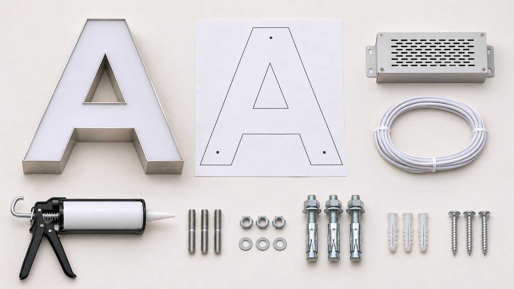
Channel letter installation accessories checklist
Confirm each item against the approved drawing and packing list. A component shown in a guide or photograph is not automatically included in every sign order.
| Accessory | Purpose and points to confirm |
|---|---|
| Full-size installation template | A paper mounting or drilling template sets out the letter spacing, baseline, fixing holes and cable exits. Confirm its scale, viewing direction, overall dimensions and revision before drilling. |
| Threaded mounting studs or threaded rod | Connect the letter or its mounting assembly to the specified fixing system. Match the thread, material, exposed length and engagement to the drawing; do not substitute a rod simply because it fits the hole. |
| Nuts and washers | Clamp or lock connections where the design requires them. Through-wall fixing may need accessible rear nuts and washers. Other fixing systems can be installed from the front without a nut behind the wall. |
| Stand-off spacers or mounting brackets | Control the distance from the wall and support the intended lighting effect. Keep the specified spacing consistent, especially for halo-lit letters. Refer to the backlit letter halo gap guide when confirming this detail. |
| Wall plugs, expansion anchors or another approved wall-fixing system | Transfer the load to a suitable substrate. Select the complete anchor-and-screw system for the actual wall, load and exposure; a plastic plug and a metal expansion anchor are not interchangeable. |
| Self-tapping or self-drilling screws | Secure specified brackets, back panels or support-frame components. Match the screw to the support material, thickness, corrosion conditions and required engagement. |
| Silicone sealant or a specified adhesive | May seal penetrations or provide a specified bond. Confirm the product’s intended use, coating compatibility, surface preparation and curing conditions. Ordinary sealant is not a substitute for a designed load-bearing connection. |
| Driver, cables and connectors | Check what is supplied and what the installer provides: the matched driver, low-voltage leads, connectors, cable protection, junction enclosure and access for maintenance. Use the actual equipment labels and our channel letter power supply guide when planning the electrical arrangement. |
Choosing studs, nuts and wall fixings
When the back of the wall cannot be reached
A rear retaining nut is unnecessary only when the selected fixing design does not require one. For example, the project may use a suitable front-access bracket or a specified blind-fixing system.
Do not simply leave a nut out of a through-wall design. Also distinguish a nut behind the wall from a nut on the accessible face that sets an expansion anchor, clamps a bracket or locks the connection. Those required nuts must remain in place. Resolve wall-back access before the mounting hardware is selected.
Large or heavy letters need a designed mechanical fixing
Large, heavy or wind-exposed letters and logos need a mechanical fixing or support-frame design matched to the load-bearing substrate. On suitable concrete, that may mean specified metal expansion anchors or another approved anchoring system. Hollow masonry, stud walls, thin cladding and glass require their own fixing details; the decorative face alone may not be a suitable load-bearing support.
Follow the selected anchor manufacturer’s requirements for drilling, embedment, cleaning, spacing and installation torque. The fischer concrete-anchor installation information, for example, explains that the specified installation torque is part of setting that anchor system. It is not a universal torque for all sign fixings.
Do not treat a generic plastic expansion plug as the default for every large sign. The fischer wall-plug selection information lists different conditions for different substrates and compatible screws. The complete fixing arrangement must suit the project; multiplying a catalogue value by the number of screws does not establish a sign’s design capacity.
Where self-tapping screws fit
Self-tapping screws can form threads in suitable material; self-drilling screws also have a drill point. Neither term means that the screw can be driven straight into any wall. Use the specified pilot hole or drilling procedure, material thickness and engagement. Do not rely on an unverified thin panel to support a heavy letter or logo.
Silicone sealant and structural adhesive have different roles
Silicone sealant is often discussed as “glass glue”, but that name does not identify its approved purpose. A weather-sealing product, a general bonding product and a structural adhesive may have different substrate, joint and curing requirements.
Use only the adhesive or sealant specified for the actual surfaces, including any paint or coating. The Sika guidance on structural silicone compatibility and joint design illustrates why material testing, joint geometry and curing conditions matter. It does not make that product a general approval for every illuminated sign.
Keep required temporary support in place during curing. A surface skin or tack-free bead does not prove that the full adhesive joint is ready to carry the load. Do not use a general sealant to replace the mechanical fixing required by the mounting design, and do not block drainage, ventilation or service access when sealing.
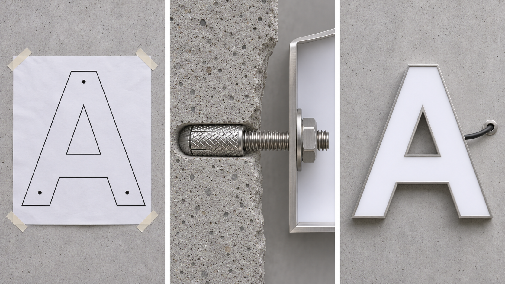
Installation sequence with accessory checks
Use the following sequence alongside the approved drawings and the instructions for the selected fixing and electrical systems.
- Confirm the support and installation method. Establish the actual load-bearing wall material, letter weight, access behind the wall and cable route. Locate concealed services before drilling and isolate affected electrical circuits.
- Unpack and identify the components. Match each letter, mounting part and electrical component to the packing list. Check for damage, missing hardware, mismatched threads and drawing revisions before taking the assembly to the wall.
- Position the full-size template. Verify the printed scale against the stated dimensions. Level the baseline, check the overall layout and confirm the viewing direction. Mark fixing holes separately from cable exits.
- Prepare the fixing and cable holes. Drill and prepare the substrate exactly as required by the selected anchoring system. Clean holes where its instructions require it; protect the cable penetration with the specified sleeve or grommet.
- Fit the specified anchors, studs, brackets and spacers. Follow the mounting drawing for their assembly order. Keep required washers and nuts, use the correct thread engagement, and check the stand-off distance before final tightening.
- Trial-fit and secure the letters. Check alignment and cable clearance while the assembly remains supported. Tighten to the fixing instructions without distorting the letter body or damaging the finish.
- Complete sealing and allow the specified cure. Prepare the actual bonding surfaces, seal only the required locations and retain any curing support. Use the product instructions for the actual site conditions rather than a general “wait overnight” rule.
- Complete the electrical work and inspect. Have the mains connection completed by a qualified electrician to local requirements. Confirm the matched driver, polarity where applicable, protected connections and maintenance access. After mechanical and electrical checks, test illumination and retain the installation record.
Confirm what is supplied before the sign ships
Ask the supplier to mark each accessory as included, optional or supplied on site. Record the hardware quantities, thread sizes, materials, wall-fixing specification, spacers, template revision and electrical connection details. Local wall anchors and adhesives should be selected for the actual substrate and installation conditions, rather than assumed to be universal factory-supplied items.
The channel letter technical reference helps organise the drawing, construction and installation information. Send HLW SIGN the artwork, overall dimensions, location, wall photographs and any access restrictions so the mounting arrangement and accessory scope can be confirmed with the quotation and approved drawing.
Ask HLW SIGN to confirm the installation accessories for your letters or logo.